Stick
PPM Stick
General case: BCS unit sends commands directly to the 1x air unit
Follow the steps below to perform a correct stick configuration on the BCS and 1x units.
BCS unit (BCS PDI Builder configuration)
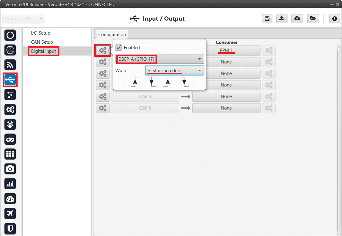
Go to Input/Output menu \(\rightarrow\) Digital Input section.
Make sure that the following parameters have been configured:
Producer: CAP 1
Enabled
Select the pin to which the transmitter is connected (normally EQEP A (i.e., GPIO 17))
Edge detection: First rising edge
Consumer: PPM 1
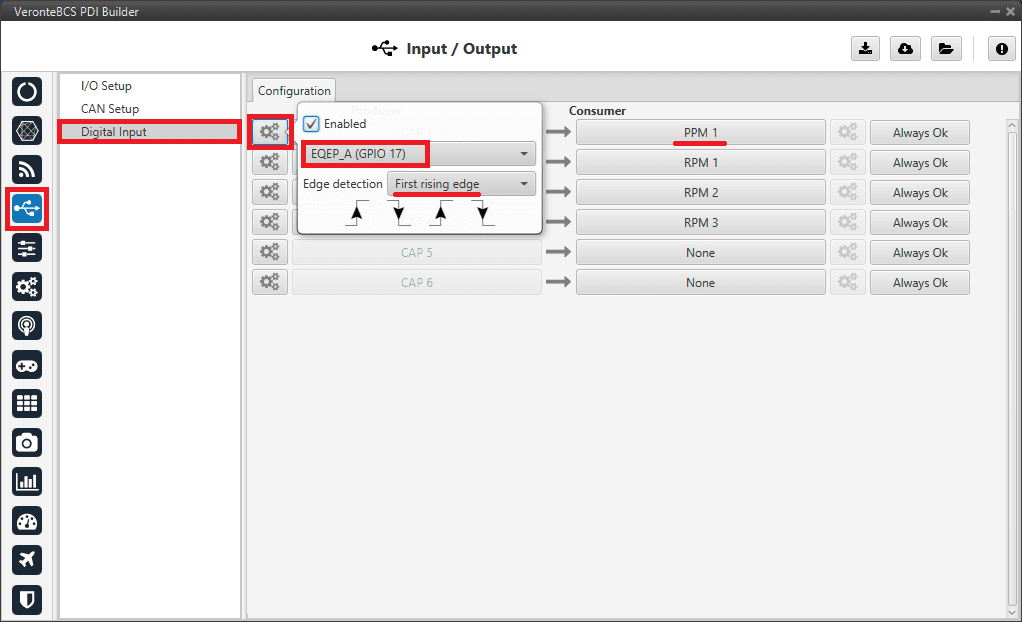
Stick - Digital Input configuration
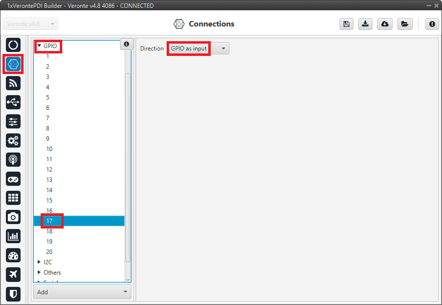
Go to Connections menu \(\rightarrow\) GPIO section.
Verify that the pin to which the transmitter is connected, in this case GPIO 17 (i.e., EQEP A), is set as input.
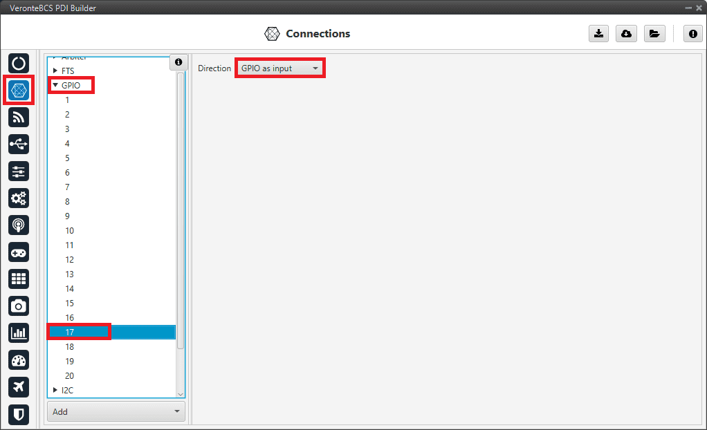
Stick - GPIO/EQEP configuration
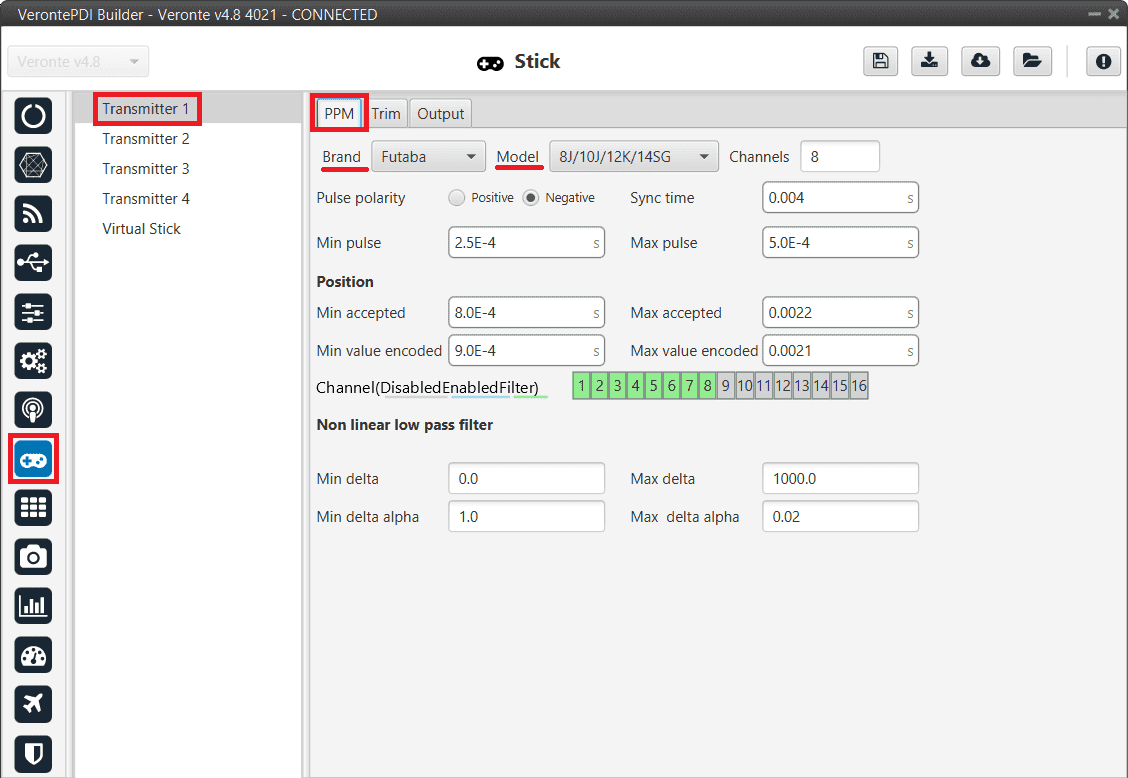
Go to Stick menu \(\rightarrow\) Transmitter 1 section \(\rightarrow\) PPM tab.
Select the brand of transmitter that applies.
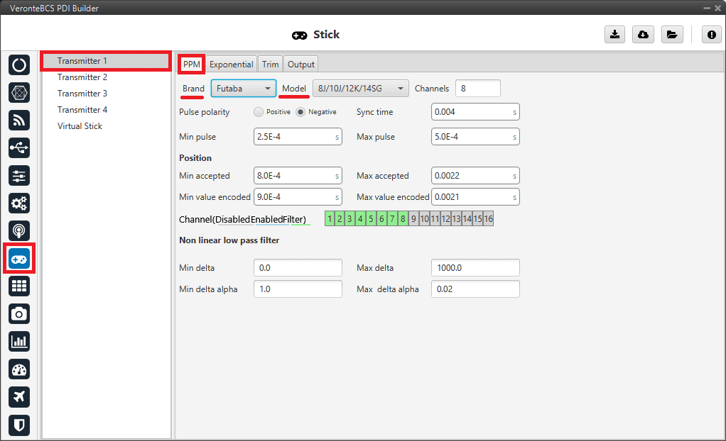
Stick - PPM configuration
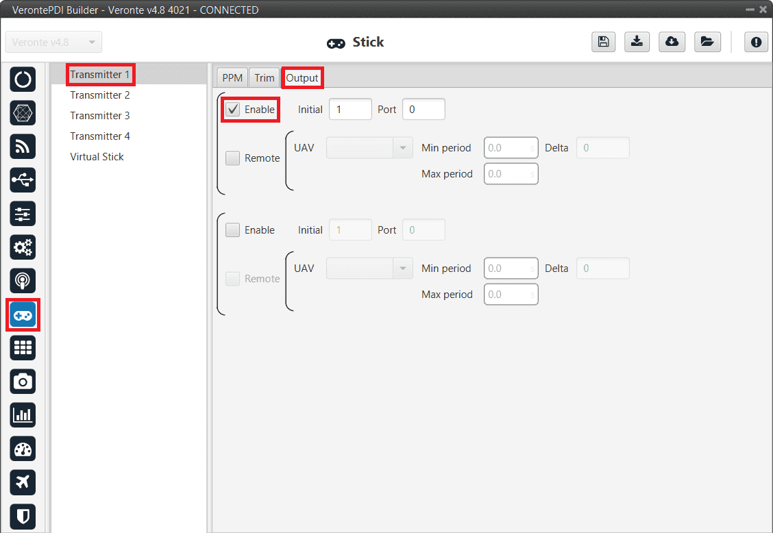
Go to Stick menu \(\rightarrow\) Transmitter 1 section \(\rightarrow\) Output tab.
Click on Enable and on Remote to send the stick information to the air unit. Please check the recommended values for the configurable parameters described in the Ouput tab of the Stick section.
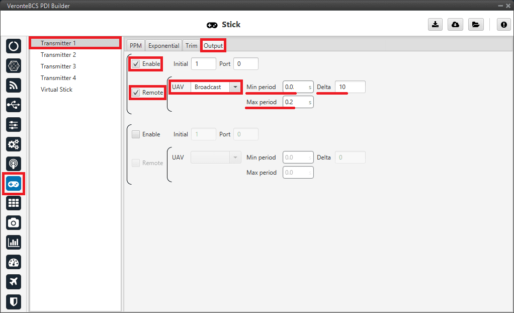
Stick - Output configuration
If all these settings are correct, users can check that ‘Stick PPM 1 not detected’ variable of the BCS unit will be true.

Stick PPM 1 not detected variable - True
1x air unit (1x PDI Builder configuration)
Go to Stick menu \(\rightarrow\) Transmitter 1 section \(\rightarrow\) PPM tab.
Select the brand of transmitter that applies (make the same configuration as the BCS unit).
Go to Stick menu \(\rightarrow\) Transmitter 1 section \(\rightarrow\) Output tab.
Just click on Enable.
Stick - Output configuration
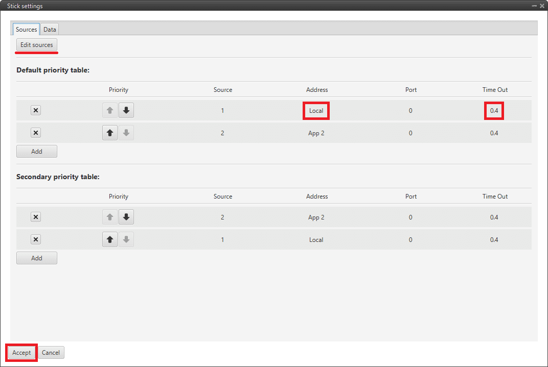
Go to Block Programs menu \(\rightarrow\) Stick program \(\rightarrow\) Double click on the Stick block \(\rightarrow\) Edit sources.
Input the ground unit address to receive the stick information from that source and put it as the highest priority in the priority table. We recommend a Time Out of 0.4 s.
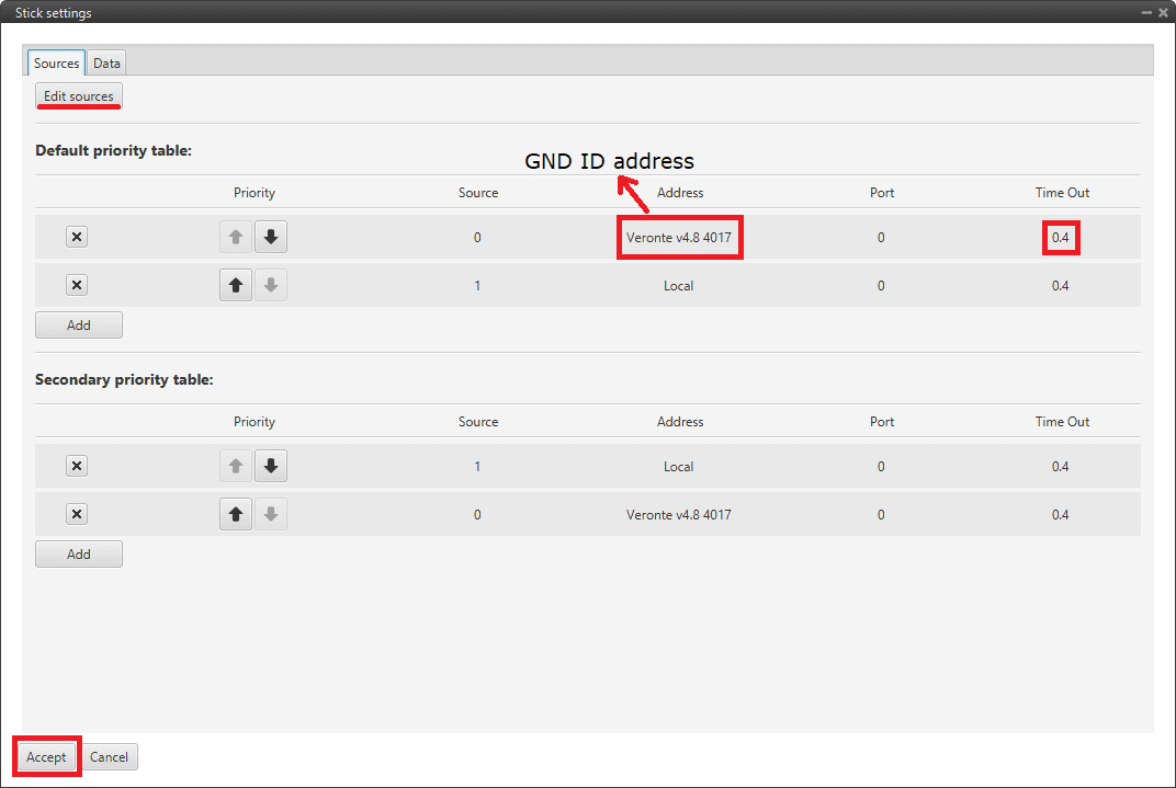
Stick block configuration
Then, if all is correct, users can check that ‘Stick not detected’ variable of the 1x air unit will be true.

Stick not detected variable - True
And that means that the communication between the BCS and the 1x air unit is correctly configured.
Simulation case (HIL)
In this case, the user is only using one Veronte BCS.
So users will have to follow steps 1, 2 and 3 explained above for the BCS unit, but also steps 2 and 3 of the 1x air unit configuration. However, instead of entering the BCS unit address, select the Local option.
On-board PPM receiver case
In that case, follow the next steps:
BCS unit (BCS PDI Builder configuration)
Go to Stick menu \(\rightarrow\) Transmitter 1 section \(\rightarrow\) PPM tab.
Select the brand of transmitter that applies.
Stick - PPM configuration
1x air unit (1x PDI Builder)
Go to Input/Output menu \(\rightarrow\) Digital Input section.
Make sure that the following parameters have been configured:
Producer: CAP 1
Enabled
Select the pin to which the transmitter is connected (normally EQEP A (i.e., GPIO 17))
Edge detection: First rising edge
Consumer: PPM 1
Stick - Digital Input configuration
Go to Connections menu \(\rightarrow\) GPIO section.
Verify that the pin to which the transmitter is connected, in this case GPIO 17 (i.e., EQEP A), is set as input.
Stick - GPIO/EQEP configuration
Go to Stick menu \(\rightarrow\) Transmitter 1 section \(\rightarrow\) PPM tab.
Select the brand of transmitter that applies.
Stick - PPM configuration
Go to Stick menu \(\rightarrow\) Transmitter 1 section \(\rightarrow\) Output tab.
Just click on Enable.
Stick - Output configuration
If all these settings are correct, users can check that ‘Stick PPM 1 not detected’ variable of the 1x air unit will be true.
Stick PPM 1 not detected variable - True
Go to Block Programs menu \(\rightarrow\) Stick program \(\rightarrow\) Double click on the Stick block \(\rightarrow\) Edit sources.
Input the address as Local to receive the stick information from that source and put it as the highest priority in the priority table. We recommend a Time Out of 0.4 s.
Stick block configuration
Then, if all is correct, users can check that ‘Stick not detected’ variable of the 1x air unit will be true.
Stick not detected variable - True
And that means that the communication between the BCS and the 1x air unit is correctly configured.
USB joystick
Veronte software is able to detect USB devices such as joysticks. The axis of these devices can be read and configured to send stick information to Veronte Autopilot 1x.
To configure them:
Connect the USB joystick to the computer.
Configure a Virtual Stick as explained in Virtual Stick Integration.
Virtual Stick
To configure a virtual stick, follow the next steps:
Go to Stick menu \(\rightarrow\) Virtual Stick section \(\rightarrow\) Input variable tab.
Enable the virtual stick and enter an update period (we recommend 0.02 s).
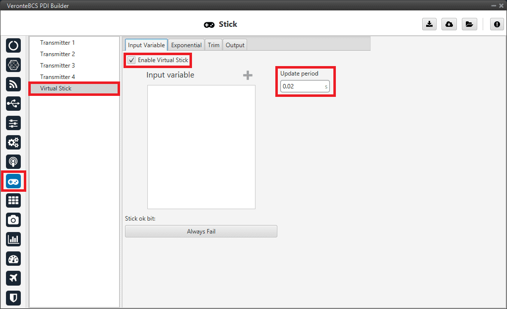
Virtual Stick configuration
Go to Stick menu \(\rightarrow\) Virtual Stick section \(\rightarrow\) Output tab.
Just click on Enable.
Go to Block Programs menu \(\rightarrow\) Stick program \(\rightarrow\) Double click on the Stick block \(\rightarrow\) Edit sources.
Input App 2 to receive the stick information from the virtual stick widget and put it as the highest priority in the priority table. We recommend a Time Out of 0.4 s.
Configure a Virtual Stick Widget.
Please find an example of how to configure it in Virtual stick widget in the Integration examples section of the Veronte Ops manual.
If the user creates a virtual stick to process the information received through a different channel than PPM (e.g., by CAN or ADC), the user will also have to:
Go to Stick menu \(\rightarrow\) Virtual Stick section \(\rightarrow\) Input variable tab.
Add the variables containing the stick information in Input Variable.
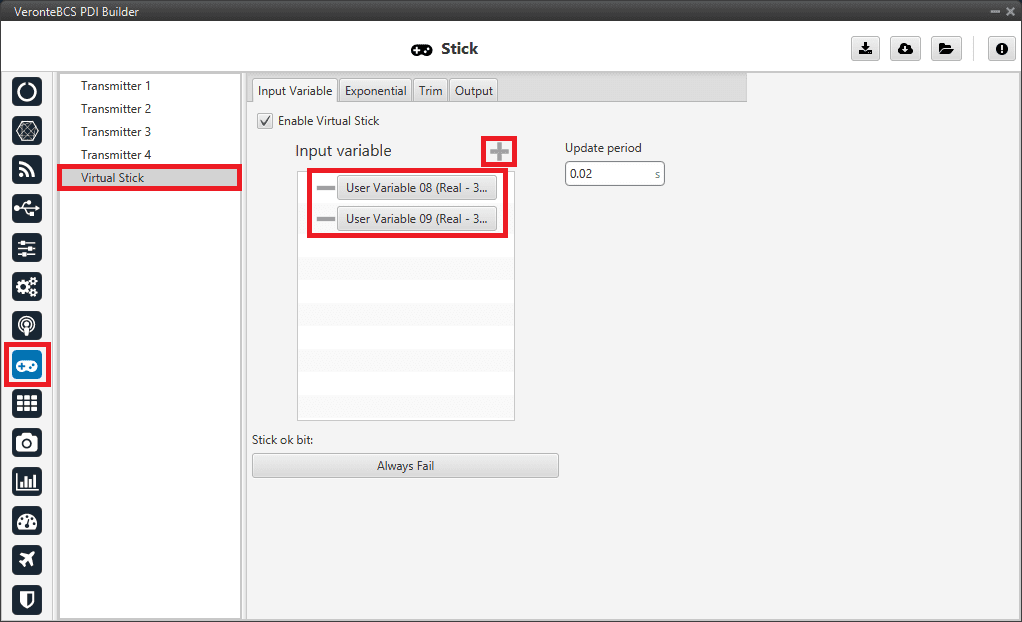
Virtual Stick with Input variables configuration